Notes on the Variscite DART-MX6 GPIO Interface
Friday April 22, 2016

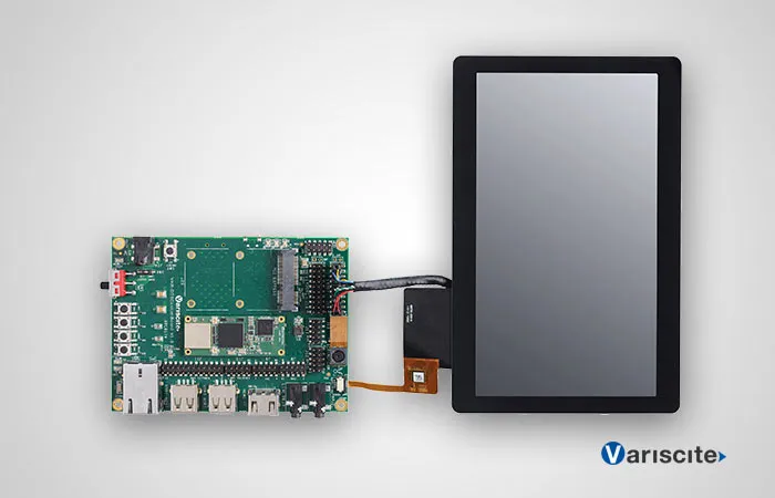
Because of reasons, I have a Variscite VAR-DTK-MX6 evaluation kit for the DART-MX6 system on module (SOM) sitting on my desk at home. It’s a neat little board. The DART-MX6 is small, measuring 20mm by 50mm and runs a dual-core ARM Cortex-9 processor. This makes it a bit more powerful than, for instance, a Raspberry Pi, but it is only $27. The SOM is meant to be used as a component in an embedded application when some device or another that needs a 32-bit microprocessor.
The evaluation kit is about the size of two Raspberry Pi boards and mounts the SOM. It provides HDMI, several USB ports, Ethernet, PCI Express, and more pins than I can count. It also comes with a touchscreen that connects to the board.
Variscite provides images running both Yocto and Android. It would be nice if it ran NetBSD, but that’s only because I like such things. For this project, my primary concern is Yocto.
The DART-MX6 provides a crazy number of GPIO pins. The kernel reports 224:
root@var-som-mx6:~# cat /sys/kernel/debug/gpio
GPIOs 0-31, platform/209c000.gpio, 209c000.gpio:
  gpio-6   (2194000.usdhc cd    ) in  lo
  gpio-25  (phy-reset           ) out lo
  gpio-28  (usb_h1_vbus         ) out lo

GPIOs 32-63, platform/20a0000.gpio, 20a0000.gpio:

GPIOs 64-95, platform/20a4000.gpio, 20a4000.gpio:

GPIOs 96-127, platform/20a8000.gpio, 20a8000.gpio:
  gpio-101 (tlv320aic3x reset   ) out lo
  gpio-111 (usb_otg_vbus        ) out lo

GPIOs 128-159, platform/20ac000.gpio, 20ac000.gpio:

GPIOs 160-191, platform/20b0000.gpio, 20b0000.gpio:
  gpio-178 (sysfs               ) out lo

GPIOs 192-223, platform/20b4000.gpio, 20b4000.gpio:
  gpio-200 (wlan-en-regulator   ) out lo
root@var-som-mx6:~#
In particular, the documentation states there are two LEDs (D1 and D2) and three physical buttons on the evaluation board that can be read and set via GPIO. However, figuring out which button is which GPIO pin is kind of opaque. The schematics provided by Variscite provide some insight, but not enough.
The schematics state that the following are labels equivalent:
The other buttons are hardwired to reset and on/off so the don’t matter much from this perspective. Of course, those GPIO identifiers are still insufficient to determine what pin number Linux uses to identify the port. Given an label of the form GPIOm[n], the pin will be internally identified as number (m - 1) * 32 + n. So, for instance, D1 is GPIO pin (4 - 1) * 32 + 27 = 123.
So, the final mapping is:
Despite this complexity, you can access and manipulate the GPIO using a simple shell script. This one, written for the Raspberry Pi, will work just fine on any Linux system that exports the GPIO pins via sysfs, which Yocto does on the DART-MX6.